Products
Cold and Hot Water Coil | Coils
How to produce CROSS FIN TUBE Heat Exchanger
Pressure-proof test pressure and airtightness test pressure of CROSS FIN TUBE Heat Exchanger (Cold and Hot Water Coil)
| D.X COIL, EVA/COIL | HOT/COLD WATER COIL, STEAM COIL |
CONDENSER COIL |
|---|---|---|
| Pressure-proof test : 20Kg/㎠ Airtightness test : 15kg/㎠ |
Pressure-proof test : 20Kg/㎠ Airtightness test : 15kg/㎠ |
Pressure-proof test : 33Kg/㎠ Airtightness test : 25kg/㎠ |
Total Heat Transfer Area of The Coil
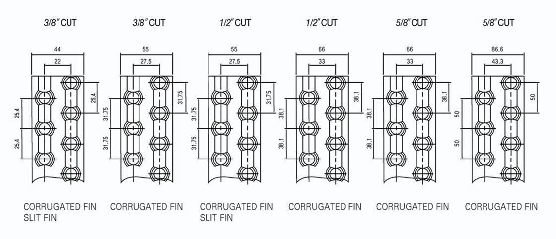
Standard FIN Specification (Cold and Hot Water Coil)
TRANSFER AREA [㎡ / m] (Cold and Hot Water Coil)
| PIPE PITCH | TUBE \ FP | 2.1 | 2.5 | 3 | 3.2 | 4.2 | 4.5 | 5.5 | 6 | 6.5 | 8 | 8.5 | 10 | 12 | 15 |
|---|---|---|---|---|---|---|---|---|---|---|---|---|---|---|---|
| 22 x 25.4 | 3/8” | 0.5337 | 0.4526 | 0.3831 | 0.361 | 0.2821 | 0.2684 | 0.2249 | 0.208 | 0.1951 | 0.1639 | 0.1568 | 0.138 | 0.1213 | 0.1034 |
| 27.5 x 31.75 | 3/8” | 0.8414 | 0.7188 | 0.5984 | 0.5629 | 0.4375 | 0.4104 | 0.3415 | 0.3156 | 0.2938 | 0.2541 | 0.2326 | 0.2033 | 0.1746 | 0.146 |
| 27.5 x 31.75 | 1/2" | 0.7896 | 0.669 | 0.5657 | 0.5328 | 0.4167 | 0.3945 | 0.3298 | 0.3045 | 0.2857 | 0.2396 | 0.2289 | 0.2009 | 0.1759 | 0.1494 |
| 33 x 38.1 | 1/2" | 1.1453 | 0.9689 | 0.8146 | 0.7663 | 0.5964 | 0.5607 | 0.4665 | 0.4312 | 0.4013 | 0.3341 | 0.3169 | 0.2763 | 0.2378 | 0.1991 |
| 33 x 38.1 | 5/8” | 1.0924 | 0.9244 | 0.7804 | 0.7346 | 0.5733 | 0.5412 | 0.4512 | 0.4175 | 0.3897 | 0.326 | 0.3107 | 0.2717 | 0.2368 | 0.1997 |
| 43.3 x 50 | 5/8” | 1.9825 | 1.6708 | 1.4036 | 1.3186 | 1.0186 | 0.9589 | 0.792 | 0.7296 | 0.6781 | 0.5601 | 0.5251 | 0.4591 | 0.3945 | 0.3258 |
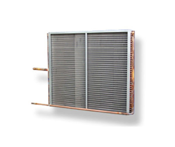
Outside view of COIL
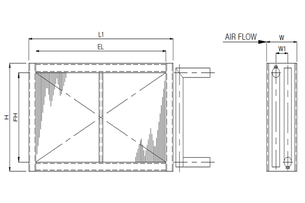
Outside Measurement of Coil (Cold and Hot Water Coil)
| EL(mm) | L(mm) | H(mm) |
|---|---|---|
| 500 ~ 2000 | EL + 100 | EH + 80 |
| 2001 ~ 4000 | EL + 100 | EH + 100 |
| ROW | 1 | 2 | 3 | 4 | 6 | 8 | 10 | 12 |
|---|---|---|---|---|---|---|---|---|
| W(mm) | 80 | 110 | 140 | 180 | 240 | 310 | 370 | 440 |
Diameter of Connecting Pipe (Cold and Hot Water Coil)
| Flow rate (Flow rate)( L/min) |
Diameter (Diameter)(mm) |
|---|---|
| 0 ~ 150 | 40A |
| 151 ~ 250 | 50A |
| 251 ~ 400 | 65A |
| 401 ~ 600 | 80A |
| 601 ~ 950 | 100A |
Outside View of COIL (Cold and Hot Water Coil)
COIL Size and Air Passing Area (Cold and Hot Water Coil)
| NUMBER OF STEPS |
10 | 12 | 14 | 16 | 18 | 20 | 22 | 24 | 26 | 28 | 30 | 32 | 34 |
|---|---|---|---|---|---|---|---|---|---|---|---|---|---|
| EFFECTIVE LENGTH |
381 | 457 | 33 | 610 | 689 | 762 | 838 | 914 | 990 | 1067 | 1143 | 1219 | 1295 |
| 500 | 0.192 | 0.23 | 0.268 | 0.306 | 0.344 | 0.382 | 0.418 | 0.456 | 0.496 | 0.534 | 0.57 | 0.61 | 0.648 |
| 600 | 0.231 | 0.278 | 0.322 | 0.367 | 0.413 | 0.459 | 0.502 | 0.547 | 0.595 | 0.641 | 0.664 | 0.732 | 0.778 |
| 700 | 0.269 | 0.322 | 0.375 | 0.429 | 0.482 | 0.535 | 0.585 | 0.639 | 0.695 | 0.748 | 0.798 | 0.854 | 0.907 |
| 800 | 0.307 | 0.368 | 0.428 | 0.49 | 0.551 | 0.611 | 0.669 | 0.73 | 0.794 | 0.855 | 0.922 | 0.976 | 1.037 |
| 900 | 0.346 | 0.414 | 0.483 | 0.551 | 0.619 | 0.688 | 0.753 | 0.821 | 0.893 | 0.961 | 1.026 | 1.098 | 1.167 |
| 1000 | 0.381 | 0.57 | 0.533 | 0.61 | 0.689 | 0.762 | 0.838 | 0.914 | 0.99 | 1.067 | 1.143 | 1.219 | 1.295 |
| 1100 | 0.423 | 0.506 | 0.59 | 0.672 | 0.757 | 0.841 | 0.92 | 1.003 | 1.091 | 1.175 | 1.254 | 1.342 | 1.426 |
| 1200 | 0.461 | 0.552 | 0.643 | 0.735 | 0.826 | 0.917 | 1.003 | 1.095 | 1.191 | 1.282 | 1.366 | 1.464 | 1.555 |
| 1300 | 0.499 | 0.598 | 0.697 | 0.796 | 0.895 | 0.993 | 1.087 | 1.186 | 1.29 | 1.389 | 1.482 | 1.586 | 1.685 |
| 1400 | 0.538 | 0.644 | 0.751 | 0.857 | 0.963 | 1.07 | 1.171 | 1.277 | 1.389 | 1.495 | 1.596 | 1.708 | 1.815 |
| 1500 | 0.576 | 0.69 | 0.804 | 0.918 | 1.302 | 1.146 | 1.254 | 1.368 | 1.489 | 1.602 | 1.71 | 1.83 | 1.944 |
| 1600 | 0.615 | 0.736 | 0.858 | 0.979 | 1.101 | 1.223 | 1.338 | 1.459 | 1.687 | 1.709 | 1.824 | 1.957 | 2.074 |
| 1700 | 0.653 | 0.782 | 0.911 | 1.041 | 1.17 | 1.299 | 1.421 | 1.551 | 1.687 | 1.816 | 1.938 | 2.074 | 2.203 |
| 1800 | 0.691 | 0.828 | 0.965 | 1.102 | 1.238 | 1.375 | 1.505 | 1.642 | 1.786 | 2.023 | 2.052 | 2.196 | 2.333 |
| 1900 | 0.73 | 0.874 | 1.019 | 1.163 | 1.307 | 1.452 | 1.589 | 1.733 | 1.885 | 2.029 | 2.166 | 2.318 | 2.463 |
| 2000 | 0.807 | 0.92 | 1.072 | 1.224 | 1.376 | 1.528 | 1.672 | 1.824 | 1.984 | 2.136 | 2.28 | 2.44 | 2.592 |
| 2100 | 0.845 | 0.966 | 1.126 | 1.265 | 1.445 | 1.605 | 1.756 | 1.915 | 2.083 | 2.243 | 2.394 | 2.582 | 2.723 |
| 2200 | 0.883 | 1.012 | 1.18 | 1.348 | 1.513 | 1.681 | 1.84 | 2.007 | 2.183 | 2.35 | 2.503 | 2.684 | 2.851 |
| 2300 | 0.923 | 1.058 | 1.233 | 1.408 | 1.582 | 1.757 | 1.923 | 2.098 | 2.282 | 2.451 | 2.622 | 2.906 | 2.981 |
| 2400 | 0.96 | 1.104 | 1.287 | 1.496 | 1.651 | 1.834 | 2.007 | 2.189 | 2.361 | 2.563 | 2.736 | 2.928 | 3.111 |
| 2500 | 0.999 | 1.15 | 1.34 | 1.53 | 1.72 | 1.91 | 2.09 | 2.28 | 2.48 | 2.67 | 2.85 | 3.05 | 3.24 |
| 2600 | 1.037 | 1.196 | 1.394 | 1.591 | 1.788 | 1.987 | 2.174 | 2.371 | 2.579 | 2.777 | 2.94 | 3.172 | 3.37 |
| 2700 | 1.047 | 1.242 | 1.447 | 1.653 | 1.857 | 2.063 | 2.257 | 2.463 | 2.679 | 2.884 | 3.078 | 3.294 | 3.499 |
| 2800 | 1.057 | 1.268 | 1.501 | 1.714 | 1.926 | 2.139 | 2.341 | 2.554 | 2.778 | 2.991 | 3.192 | 3.416 | 3.629 |
| 2900 | 1.114 | 1.334 | 1.555 | 1.775 | 1.995 | 2.216 | 2.425 | 2.645 | 2.677 | 3.097 | 3.306 | 3.538 | 3.759 |
| 3000 | 1.152 | 1.38 | 1.608 | 1.83 | 2.064 | 2.292 | 2.508 | 2.738 | 2.976 | 3.204 | 3.42 | 3.66 | 3.888 |
Selection Criteria of CROSS-FIN COIL
-
Front passing wind speed of COIL
If the front passing wind speed of the cooling COIL is 2~3m / s or more, install an eliminator behind the cooling COIL. Select the heating coil within 4m/s.
-
Evaporation temperature of refrigerant
If the evaporation temperature of the refrigerant is low, the power cost increases due to the low efficiency of the refrigerator although the ability of the cooling coil increases. On the contrary, if the evaporation temperature becomes higher, the power cost is reduced but a large heat transfer area should be selected. Therefore, please consider the economic aspect of the evaporation temperature, and also note that condensation occurs on the surface of the FIN when the evaporation temperature is low, which will also require measures.
-
The flow direction of refrigerant and air
To increase the efficiency of COIL, please set the flow of refrigerant or heat medium and air so as to become COUNTER FLOW.
-
Selection of required flow rate
For the water speed of the pipe in the cold and hot water COIL, 0.8 ~ 1.2 m/s is good for the efficiency of the water coil as well as for the piping and pump equipment cost.
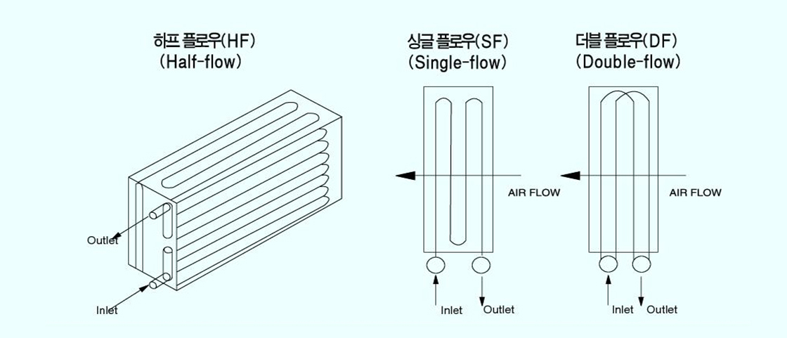
Divide the required flow rate by the number of COIL steps, check the flow rate, and select the shape of the HEADER from the half flow (HF), single flow (SF) and double flow (DF). -
Coil capacity margin
Depending on a load of cooling and heating of the COIL, add 50% for 1 row, 50% for 2 rows, and 20% for 4 rows or more to the selected number of rows required, whichmakes the final number of rows.
※ The header of cold and warm water coil can use the following three circuits according to the flow velocity of passing fluid.
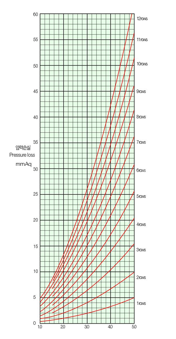
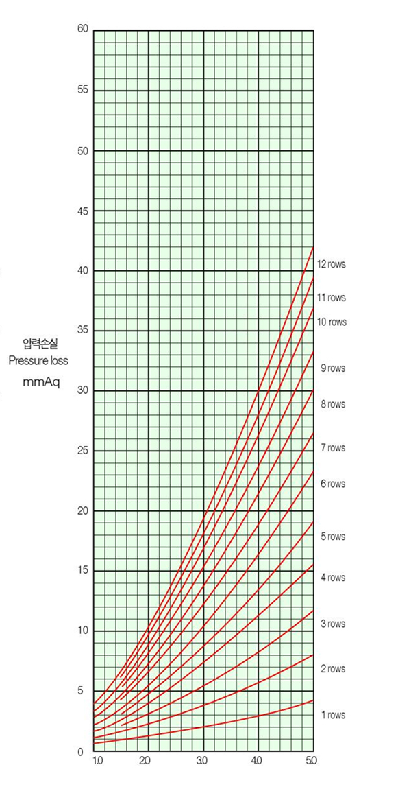
COIL Air Pressure Loss Table
If the FIN surface is wet
(COOLING WATER COIL, DX /COIL)
If the FIN surface is dry
(HOT WATER COIL, STEAM COIL)
Correction Coefficient Table of The Air Static Pressure Loss According to FIN PITCH (Cold and Hot Water Coil)
| FIN PITCH | 2.0 | 2.5 | 3.0 | 3.5 | 4.0 | 4.5 | 5.0 |
|---|---|---|---|---|---|---|---|
| Correction coefficient | 1.7 | 1.33 | 1.13 | 1.00 | 0.91 | 0.83 | 0.77 |
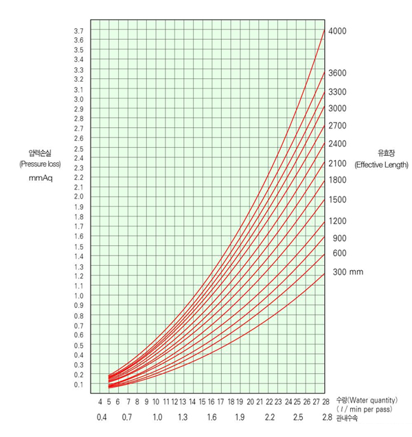
Pressure loss in cold and hot water coils
Calculation Method of Pressure Loss in Cold and Hot Water Coils
When using a cold and hot coil, the contracted pressure loss is obtained from the quantity for 1 tube pass and the effective length of the tube.
- Cooling heat : 38,000 (kcal/h)
- Coil specification : 6ROW x 18PASSES x 0.95m
- Quantity : 38,000/(60 x 5) = 126.7(ℓ/min)
- Temperature difference of hot/cold water inlet and outlet : 5℃
- Quantity per tube : 126.7 / 18 = 7.04 (ℓ/min)
- Since the tube length is 0.95m, the water pressure loss difference from the below chart is 0.15mmAq
- Water pressure loss difference 0.15mmAq
- Total pressure loss (Total pressure loss ) = 0.15 x 6ROW = 0.9 mmAq